7 Best Heat Exchanger Types and Their Functions
Heat exchangers quietly support power plants, refineries, data centers, hospitals, and everyday heating systems. Their performance affects energy use, operating costs, safety, and equipment life. The International Energy Agency’s Energy Efficiency 2023 report states that industry consumed about 37% of global final energy in 2022. That figure makes efficient thermal management impossible to ignore. The U.S. Department of Energy’s Waste Heat Recovery report also estimates that industrial facilities can lose 20% to 50% of supplied energy as waste heat. The exact loss varies widely. Poor insulation, fouling, leakage, and unstable flow can change the result.
Ramesh K. Shah, a respected heat-transfer specialist, defines the principle clearly: “A heat exchanger is a device that transfers energy from one fluid to another.” This simple statement explains the core Heat Exchanger Function. One fluid may heat water through a stainless-steel plate. Another may cool hydraulic oil inside a shell-and-tube bundle. The choice is never universal. A compact plate exchanger may suit clean liquids, while a shell-and-tube design can tolerate higher pressures and tougher maintenance conditions. Air-cooled units reduce water demand, but they may need larger surfaces and stronger fans. That trade-off matters.
This guide examines seven widely used heat exchanger types and their functions. It compares their operating principles, practical strengths, limitations, and typical applications. Some choices look efficient on paper. Field conditions can disagree. That is where careful design begins.
Heat Exchangers: Purpose, Principles, and Main Components
Heat exchangers transfer heat between fluids without normally mixing them. Their purpose is practical: heating, cooling, condensing, or recovering energy. A hot process stream may warm clean water through a thin metal wall. The wall conducts heat, while flowing fluids carry energy away. Temperature difference drives the transfer. Greater surface area usually improves performance, but it can increase cost and pressure loss.
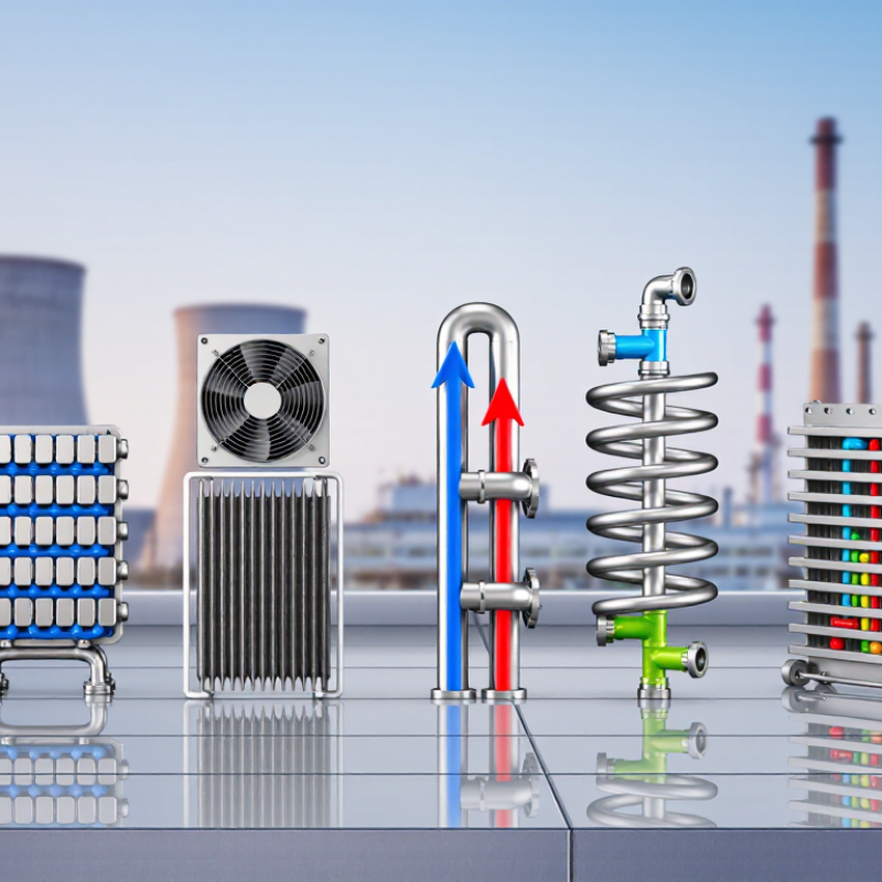
Common designs include shell-and-tube, plate, double-pipe, air-cooled, spiral, finned-tube, and scraped-surface exchangers. Shell-and-tube units suit high pressure and industrial service. Plate units provide compact heating with strong turbulence. Air-cooled models reject heat to moving air when water is limited. Scraped-surface equipment handles sticky fluids more effectively. Each type has a specific function, not a universal advantage.
Main components include heat-transfer surfaces, channels, headers, shells, tubes, baffles, gaskets, nozzles, and temperature sensors. Engineers select materials according to temperature, pressure, corrosion risk, and fluid cleanliness. They also check flow velocity, fouling allowance, and maintenance access. A small blocked passage can reduce capacity noticeably. No exchanger is perfect. A calculated design may still foul faster than expected in real service. Regular inspection, cleaning records, and measured inlet and outlet temperatures reveal that difference.
Shell-and-Tube Heat Exchangers: Structure and Industrial Functions
Shell-and-Tube Heat Exchangers: Structure and Industrial Functions
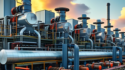
Shell-and-tube heat exchangers are among the most trusted industrial heat transfer devices. They contain a bundle of narrow tubes inside a larger shell. One fluid flows through the tubes. Another fluid moves around them. Tube sheets hold the bundle firmly, while baffles guide shell-side flow and support the tubes. This arrangement creates a large transfer area within a compact vessel.
Their functions include heating, cooling, condensing, and vaporizing process fluids. Refineries use them for oil cooling and steam condensation. Chemical plants rely on them to control reaction temperatures. Power facilities often use them in feedwater and cooling systems. The separated flow paths also reduce contamination risks between two different fluids. Proper material selection remains essential. Stainless steel may resist corrosion, while carbon steel can suit less aggressive services.
Field experience shows that performance depends on more than surface area. Poor flow distribution can leave cold zones inside the shell. Fouling can then build up on tube walls and reduce efficiency. Regular inspection should check pressure drop, vibration, leaks, and deposits. The design is reliable, but not flawless. Baffles may increase heat transfer while also causing pressure loss. Engineers must question whether maximum thermal performance justifies higher pumping energy. An overlooked detail can become an expensive maintenance problem.
Plate, Double-Pipe, and Spiral Heat Exchangers Explained
Plate, double-pipe, and spiral heat exchangers serve different process realities. Plate exchangers use thin corrugated plates to create turbulence and large transfer areas. They are compact, efficient, and easy to expand by adding plates. In food or water systems, operators can inspect the gasketed channels quickly. However, narrow passages may foul when fluids carry fibers or suspended solids. The U.S. Department of Energy reports that industrial facilities can lose 20–50% of input energy as waste heat. Better heat recovery can therefore reduce fuel demand, although real savings depend on temperature and operating hours.
Double-pipe exchangers remain practical for small duties and high-pressure services. One fluid travels inside a pipe, while the second flows through the annular space. Their simple geometry supports straightforward cleaning and reliable temperature control. The trade-off is physical size. Large duties may require many sections, increasing installation space and maintenance points. Spiral exchangers use two long channels wrapped around a central core. Their single-flow paths create strong turbulence and compact heat transfer. They often handle fouling fluids better than narrow plate channels, but access can be less convenient. This is where design judgment matters.
The International Energy Agency identifies industry as a major global energy consumer. Even modest recovery improvements can matter. Designers should check pressure drop, viscosity, corrosion, cleaning access, and seasonal load changes. A perfect theoretical calculation is not enough. Field measurements may reveal uneven flow, insulation damage, or a heat source that operates only intermittently.
7 Best Heat Exchanger Types and Their Functions
Typical overall heat-transfer coefficient ranges provide a practical comparison of common heat exchanger designs. Actual performance depends on fluid properties, temperature difference, flow arrangement, fouling, materials, and operating conditions.
How to read the chart: Plate and scraped-surface heat exchangers can provide high heat-transfer coefficients in suitable applications. Finned-tube and air-cooled designs generally have lower coefficients because air is a less effective heat-transfer medium. Double-pipe, shell-and-tube, and spiral exchangers offer flexible solutions across many industrial services.
Air-Cooled, Finned-Tube, and Regenerative Heat Exchangers
7 Best Heat Exchanger Types and Their Functions
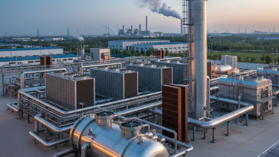
Air-cooled, finned-tube, and regenerative heat exchangers solve different thermal problems. Air-cooled units reject process heat through finned tubes and fans. They suit remote plants where cooling water is scarce. Their performance depends on airflow, ambient temperature, and fin cleanliness. A dusty fin bank can quietly reduce capacity.
Finned-tube exchangers increase surface area without greatly increasing equipment size. They work well with gases, air, steam, and liquids with moderate viscosity. However, fins can trap dirt and moisture.
Regenerative heat exchangers store heat in a rotating or fixed matrix, then release it into a separate fluid stream. This design supports strong energy recovery in furnaces, ventilation systems, and high-temperature processes.
The International Energy Agency reports that industry uses about 37% of global final energy, making recovery equipment increasingly important (IEA, Energy Technology Perspectives 2023). The U.S. Department of Energy also identifies heat recovery as a practical industrial efficiency measure (DOE, Waste Heat Recovery: Technology and Opportunities).
Tips: Check fouling risk before choosing fin spacing. Measure pressure drop, not only heat duty. For regenerative designs, inspect sealing performance regularly. Small leakage can undermine impressive laboratory efficiency. Engineers sometimes overvalue peak ratings. Real weather and maintenance conditions matter more.
Sources: International Energy Agency, Energy Technology Perspectives 2023; U.S. Department of Energy, Waste Heat Recovery: Technology and Opportunities in U.S. Industry.
How to Select the Right Heat Exchanger for Each Application
Selecting a heat exchanger starts with the duty, not the equipment catalogue.
Shell-and-tube units suit high pressure, dirty fluids, and large temperature differences.
Plate exchangers offer compact footprints and strong heat transfer for clean liquids.
Air-cooled exchangers reduce water use where cooling water is limited.
Double-pipe designs work well for smaller duties.
Spiral and scraped-surface models can handle fouling or viscous products.
Brazed-plate units are efficient, but maintenance options may be limited.
Application data should guide the choice. Record flow rate, inlet and outlet temperatures, pressure, fluid chemistry, solids content, and cleaning access.
1,638 trillion Btu
The U.S. Department of Energy’s Waste Heat Recovery report estimates 1,638 trillion Btu of annual waste heat from U.S. manufacturing.
37%
The IEA Energy Efficiency 2023 report states that industry used about 37% of global final energy in 2022.
That figure shows why heat recovery deserves early design attention. Even small thermal losses can become costly at continuous-operation sites.
Tips:
Check fouling margins with real operating data. Do not rely only on laboratory coefficients.
A compact plate unit may look ideal, yet frequent cleaning can erase its savings.
I would also question optimistic temperature approaches. A tighter approach improves recovery, but it can increase area, pressure drop, and pumping energy.
Review materials against corrosion, then verify the design under start-up, shutdown, and upset conditions.
Sometimes the less efficient exchanger is the more reliable choice.