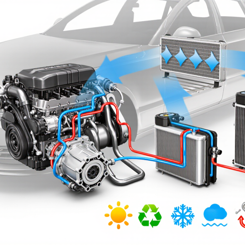
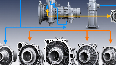
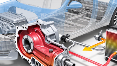
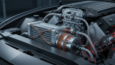
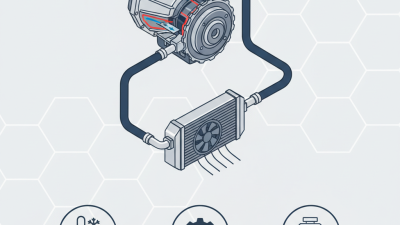
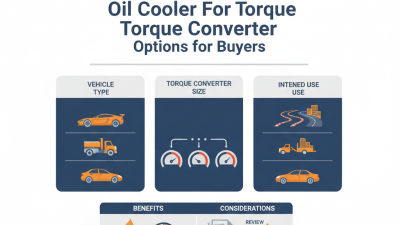
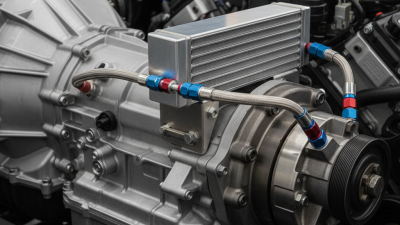
Selecting the right Oil Cooler For Torque Converter can protect a transmission from heat-related damage. A torque converter generates substantial heat during towing, stop-and-go driving, and repeated load changes. That heat must move through an efficient cooling system before it weakens fluid performance.
A suitable cooler begins with the vehicle’s operating conditions. Note the engine output, transmission type, towing weight, ambient temperature, and available airflow. A small tube-and-fin unit may suit a lightly used vehicle, while a stacked-plate cooler often provides stronger heat transfer under demanding conditions. Size matters, but bigger is not automatically better.
Check fluid flow and pressure ratings carefully. The cooler must match the transmission circuit without creating excessive restriction. Incorrect fittings can cause leaks, poor circulation, or installation damage. Measure the hose route before ordering. A sharp bend near the radiator can reduce reliability.
Material quality also deserves attention. Aluminum construction offers low weight and useful corrosion resistance when properly manufactured. Look for secure fittings, tested seals, and clear technical specifications from an established supplier. Independent test data is more valuable than vague claims.
Installation details affect real performance. Keep the cooler away from exhaust heat, protect the lines from abrasion, and allow enough airflow through the core. Inspect the fluid after installation and monitor operating temperature during a controlled drive. Do not rely on one reading. Conditions change.
There is no universal best choice. A cooler that performs well on a work truck may be unnecessary for a small commuter vehicle. Even experienced technicians can overlook airflow limitations. Recheck the design before purchase. Reliable cooling comes from matching the component to the complete system, not choosing the largest unit available.
A torque converter oil cooler removes heat from automatic transmission fluid before temperature damages the converter. During towing or stop-and-go driving, fluid temperatures can approach 110°C. Above 120°C, oxidation accelerates, according to lubricant durability data reviewed by the Society of Automotive Engineers. Oxidized fluid becomes darker and less stable. It can also leave varnish around valves and clutch passages.
The cooler must match the vehicle’s thermal load, fluid flow, and pressure range. The U.S. Department of Energy’s 2023 Vehicle Technologies Office review identifies thermal management as a major efficiency concern in electrified and conventional drivetrains. That matters here. A small cooler may fail during long climbs. An oversized unit may delay warm-up, increasing cold-fluid drag. That trade-off is easy to miss.
Check the converter’s peak input torque, towing weight, ambient temperature, and available airflow. I would also measure pressure loss, not only cooling capacity. Excessive restriction can reduce lubrication flow. SAE J1532 provides performance requirements for transmission oil-cooler hose applications, including temperature and pressure resistance. Use compatible hose materials and secure every connection against vibration. In practical inspections, a cooler often looks adequate while airflow is blocked by dirt or a heat shield. That assumption deserves another check. Some applications need a thermostatic bypass, but the correct opening temperature depends on the transmission design and fluid specification.
A torque converter creates heat whenever fluid slips between the impeller and turbine. Heavy towing, frequent reversing, and slow climbs increase this heat load quickly. Start by estimating the vehicle’s power, gross weight, duty cycle, and ambient temperature. A cooler sized for highway driving may struggle during a hot, loaded climb. Measure the transmission fluid temperature near the converter outlet when possible. A short test can reveal more than a brochure.
Flow rate matters as much as cooler size. Too little flow reduces heat transfer, while excessive restriction can raise system pressure. Check the transmission’s recommended flow range and compare it with the cooler’s pressure-drop data. Use suitable hose routing, with gentle bends and secure connections. Keep the cooler away from exhaust heat. I have seen compact installations fail because airflow was assumed, not measured. Real systems rarely behave neatly.
Tips: Choose a cooler with a practical temperature range, not merely the largest core. Confirm operating temperatures under cold starts, traffic, towing, and steep grades. A temperature probe should sit where it records meaningful fluid conditions. Leave some capacity for unusual loads, but avoid blindly oversizing. Oversizing can delay warm-up in cold weather. Review the result after installation; the first calculation may be wrong.
Choosing an oil cooler for a torque converter starts with heat, not catalog size. Measure the vehicle’s gross weight, engine output, towing load, fluid volume, and airflow around the transmission. A 2023 U.S. Department of Energy vehicle thermal-management review identifies heat rejection and packaging as continuing design constraints. That matters in a tight engine bay.
Use a stacked-plate cooler for higher thermal efficiency and limited space. A tube-and-fin cooler can suit lighter vehicles with steady airflow. For towing or repeated stop-start driving, estimate cooler capacity from measured inlet temperature and flow rate. Many transmission specialists target approximately 82–93°C fluid temperature during normal operation, while sustained temperatures above 104°C deserve investigation. A temperature gauge is better than guessing.
Size is not everything. Excessive cooling can delay fluid warm-up. Consider a thermostat or controlled bypass in cold climates. Material selection also deserves attention. Aluminum offers low weight and good heat transfer, while stainless steel provides stronger corrosion resistance but adds mass and cost. Confirm compatibility with automatic transmission fluid, seals, fittings, and road salt. ASTM D445 viscosity testing shows why fluid behavior changes sharply with temperature, so pressure-drop data must match the actual fluid grade. SAE J1532 hose requirements are useful when checking cooler-line durability.
I would leave margin. Real traffic is rarely clean laboratory testing. A cooler that works on a short road test may struggle on a mountain climb with a loaded trailer. Record temperatures before and after installation, then reassess the design. Some first estimates will be wrong. That is useful evidence.
| Selection Dimension | Option or Reference | Typical Specification or Working Range | Advantages | Limitations and Risks | Recommended Application |
|---|---|---|---|---|---|
| Cooler Type | Tube-and-fin cooler | Compact construction with oil flowing through tubes and heat-rejection fins exposed to airflow | Lightweight, economical, easy to install, and suitable for moderate heat loads | Generally provides less heat-transfer capacity than stacked-plate designs of similar size; airflow is important | Light-duty and medium-duty vehicles, auxiliary cooling, and installations with adequate airflow |
| Cooler Type | Stacked-plate cooler | Multiple internal plates create separate oil passages and external air-contact surfaces | High heat-transfer efficiency, strong internal turbulence, and good performance in a compact package | Usually costs more and may create higher pressure drop if the passages are too small | Heavy towing, high ambient temperatures, off-road equipment, and high-duty-cycle torque converters |
| Cooler Type | Oil-to-water heat exchanger | Transfers heat from transmission oil to engine coolant or another liquid circuit | Fast warm-up, stable operating temperature, and consistent performance when airflow is limited | Cooling capacity depends on coolant temperature and flow; a failure can contaminate the cooling circuit | Vehicles requiring rapid warm-up, integrated thermal management, or installation behind restricted airflow paths |
| Cooler Type | Fan-assisted air cooler | Air-to-oil cooler combined with an electric fan; common airflow ratings range from approximately 150 to 400 cubic feet per minute | Provides cooling when vehicle speed is low or natural airflow is unavailable | Requires electrical power, relay protection, suitable mounting, and sufficient clearance around the fan | Slow-moving equipment, compact engine bays, utility vehicles, and stationary or semi-stationary machinery |
| Heat Load | Light-duty service | Approximate cooler capacity: 10,000–15,000 BTU/h | Smaller package, lower cost, and easier installation | May be inadequate for towing, high ambient temperatures, or continuous heavy loads | Passenger vehicles, light utility use, and intermittent operation |
| Heat Load | Medium-duty service | Approximate cooler capacity: 15,000–25,000 BTU/h | Balanced cooling performance and packaging flexibility | Requires verification of oil flow, airflow, and mounting location | Regular towing, delivery vehicles, moderate off-road work, and frequent stop-and-go driving |
| Heat Load | Heavy-duty service | Approximate cooler capacity: 25,000–40,000+ BTU/h | Better control of oil temperature during sustained high torque and high-load operation | Larger size, greater installation complexity, and possible need for a fan or multiple cooling stages | Heavy towing, commercial vehicles, construction equipment, steep grades, and high ambient temperatures |
| Sizing Input | Torque-converter power and duty cycle | Use the converter’s continuous power, peak load, operating hours, and expected slip conditions | Produces a more accurate estimate than selecting a cooler by vehicle size alone | Undersizing can cause overheating; excessive oversizing may increase cost and pressure drop | Always evaluate before final cooler selection |
| Sizing Input | Oil flow rate | Confirm the manufacturer’s required flow and cooler circuit flow; many automotive auxiliary circuits operate in the approximate range of 3–10 gallons per minute | Helps match cooler passages, fittings, and bypass components to the hydraulic circuit | Excessive restriction can reduce lubrication flow or affect transmission operation | Check against the torque-converter and transmission service specifications |
| Sizing Input | Pressure drop | Use the cooler manufacturer’s pressure-drop curve at the actual oil viscosity and flow rate | Protects system flow and reduces the risk of inadequate lubrication | Pressure drop increases as flow rises and oil viscosity changes; cold oil can create substantially higher restriction | Select a cooler with an acceptable pressure drop across the full operating temperature range |
| Temperature Control | Thermostatic bypass | Common bypass opening temperatures are approximately 80–95°C (176–203°F), depending on the system design | Allows quicker warm-up and reduces unnecessary cooling during cold operation | Incorrect bypass calibration or installation direction can restrict flow or reduce cooling performance | Cold climates, vehicles with large external coolers, and systems requiring stable oil temperature |
| Mounting Location | In front of the radiator or condenser | Receives strong direct airflow while the vehicle is moving | Usually offers good heat rejection and simple air-cooling performance | Can reduce airflow to downstream heat exchangers and is more exposed to road debris | Suitable when grille space and airflow capacity are sufficient |
| Mounting Location | Behind the radiator or in a side air duct | Uses existing airflow but may experience higher inlet-air temperature | Provides better protection from direct impact and can simplify hose routing | Lower cooling capacity may result if airflow is weak or already heated by another heat exchanger | Suitable for protected installations with verified airflow |
| Material | Aluminum | Low-density metal with good thermal conductivity; commonly used for cooler cores and end plates | Lightweight, corrosion-resistant when properly designed, and effective for air-to-oil heat transfer | Can be vulnerable to impact, galvanic corrosion, or fatigue if mounting and material compatibility are poor | Most automotive and mobile-equipment applications where low weight matters |
| Material | Steel | High-strength material often used where impact resistance and structural durability are priorities | Strong, durable, and suitable for demanding mechanical environments | Heavier than aluminum and requires effective corrosion protection | Heavy equipment, protected chassis installations, and severe-duty environments |
| Material | Copper-brass | Traditional heat-exchanger construction with copper tubes and brass components | Good thermal conductivity and repairability in some service environments | Heavier than aluminum and more susceptible to corrosion if coolant, moisture, or dissimilar metals are not managed correctly | Specialized or legacy systems where repairability and compatibility are established |
| Connection Size | Hose and port compatibility | Common automotive cooler connections include approximately 3/8-inch and 1/2-inch hose or equivalent fittings | Correctly matched connections reduce leakage risk and unnecessary adapters | Port size alone does not confirm adequate flow; internal passage size and fitting design also matter | Match the cooler ports with the original circuit and use oil-rated hoses |
| Installation | Hose routing and protection | Keep hoses away from exhaust heat, sharp edges, moving parts, and minimum-bend-radius violations | Reduces abrasion, heat damage, kinking, and premature hose failure | Poor routing can cause leaks or flow restriction even when the cooler itself is correctly sized | Use secure clamps, abrasion protection, and heat shielding where required |
| System Verification | Temperature monitoring | Monitor oil temperature at the cooler inlet and outlet; many automatic transmission systems operate roughly within 80–105°C (176–221°F), subject to vehicle specifications | Confirms actual cooling performance under real load conditions | A single temperature reading may hide inlet-outlet differences or localized overheating | Test after installation during towing, climbing, and high-ambient operation |
| Final Decision | Selection priority | Choose in this order: heat load, flow and pressure drop, temperature control, airflow, material compatibility, mounting space, and serviceability | Creates a balanced selection based on system requirements rather than cooler appearance alone | Using only vehicle size, physical dimensions, or advertised capacity can produce an unsuitable match | Use a cooler with verified capacity, compatible materials, suitable fittings, and adequate airflow |

How to Choose an Oil Cooler for Torque Converter?
Matching Cooler Connections with the Transmission System
Choosing an oil cooler starts with the transmission connections, not the cooler’s advertised size. Check the vehicle service manual and measure both transmission ports carefully. Thread shape matters. A tapered pipe thread should never be forced into a straight-thread port. It may fit briefly, then leak under heat and pressure.
Many systems use threaded fittings, hose barbs, or compression connections. Match the cooler inlet and outlet with the existing line size. A smaller adapter can restrict fluid flow and raise operating temperature. Keep the hose path smooth, with gentle bends and no sharp kinks. Leave enough clearance from exhaust components and moving suspension parts.
Flow direction also deserves attention. Confirm which line carries hot fluid from the torque converter and which line returns cooled fluid. A temperature check with an infrared meter can help, though surface readings are not perfect. I would not trust a fitting by appearance alone. Inspect thread engagement, sealing surfaces, and pressure ratings before installation. Use transmission-fluid-compatible hoses and secure every connection with suitable clamps. After fitting the cooler, flush debris from the circuit and check for leaks during a warm test drive. Recheck the fittings afterward. Small leaks often appear only when the system reaches working temperature.
The cooler connection must match the transmission line size and fitting type to avoid restrictions, leaks, or forced adapters. The chart compares common fractional-inch transmission cooler tube sizes with their metric outside-diameter equivalents. These are nominal tube dimensions, not thread dimensions; always verify the actual fitting, hose barb, flare, or adapter specification before installation.
A larger connection can support lower fluid velocity and reduced restriction, but cooler performance also depends on core size, fluid-flow direction, hose length, and the transmission manufacturer’s recommended circuit. Match the cooler ports to the original line size whenever possible.
Installation space is the first practical constraint. Measure the gap behind the grille, radiator, and bumper before selecting a cooler. Leave room for airflow and hose bends. A core pressed against another heat exchanger may receive little fresh air. SAE J1532 testing evaluates cooler flow, pressure, vibration, and heat rejection, but laboratory clearance rarely matches a crowded engine bay. I have seen small mounting errors create sharp hose bends and later leaks.
Durability depends on temperature, pressure, vibration, and contamination. SAE technical literature commonly places automatic transmission fluid operating targets near 80–110°C, depending on load and duty cycle. ATRA service guidance often warns that excessive heat accelerates fluid oxidation and clutch wear. That risk grows during towing, stop-and-go traffic, or repeated converter slip. Use reinforced hoses, secure brackets, and fittings rated above the system’s maximum pressure. Avoid relying on plastic ties. They loosen.
Maintenance needs are easy to underestimate. Choose a cooler that allows visual inspection and flushing without removing half the front assembly. Add a temperature sensor near the return line, not only near the hot outlet. That reading may better show what reaches the transmission. SAE testing offers useful benchmarks, yet real dirt, road salt, and airflow changes remain unpredictable. I would rather accept a slightly larger core than trust a perfect catalog number. Space measurements should be repeated after installation. The first measurement can be wrong.