10 Best Hydraulic Cooling Systems for Heavy Equipment
Heavy equipment works where heat, dust, and demanding loads meet. In those conditions, a reliable Hydraulic Cooling System protects oil quality, seals, pumps, and control valves. Excessive heat can thin hydraulic fluid, accelerate wear, and reduce machine response. The damage may begin quietly, beneath a steel hood covered with dust.
As hydraulics educator Josh Cosford puts it, “Heat is the enemy of hydraulic reliability.” This warning reflects a practical truth. A cooler is not merely an accessory. It must match the machine’s flow rate, pressure conditions, ambient temperature, installation space, and duty cycle. A compact excavator needs different cooling performance than a large wheel loader working continuously under heavy load.
This guide examines 10 Best Hydraulic Cooling Systems for Heavy Equipment. Each option is considered through practical factors, including cooling capacity, fan performance, core construction, maintenance access, noise, and compatibility. Field experience matters here. A system that performs well in a clean workshop may struggle when its fins collect chaff, mud, or concrete dust.
The selection is not perfect. Real operating conditions vary, and manufacturer data may not reflect every jobsite. That limitation deserves attention. Buyers should confirm oil flow, allowable back pressure, temperature limits, and mounting requirements before choosing a unit. Small details can prevent expensive downtime.
The goal is straightforward: identify dependable cooling solutions for demanding equipment. These systems will not solve every hydraulic problem. They can, however, help control heat before it becomes a failure.
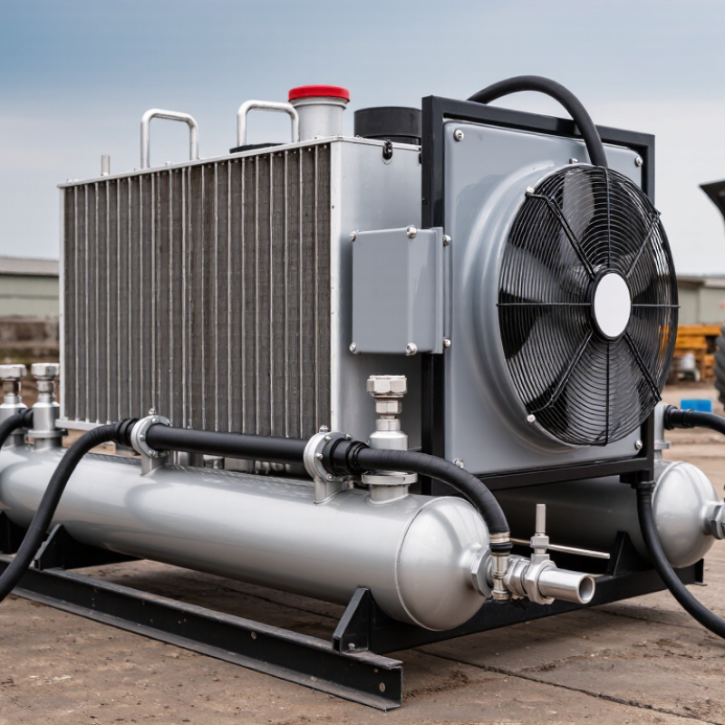
Hydraulic Cooling Fundamentals: Maintain Fluid at 40–60°C for Stable Operation
Hydraulic cooling systems keep heavy equipment dependable by controlling fluid temperature, not merely by moving air.
Aim for 40–60°C during normal operation. In this range, hydraulic oil flows smoothly, seals remain protected, and pressure response stays more consistent.
A cooler that is too small may leave the reservoir hot after repeated lifting cycles. A cooler that is oversized can add unnecessary cost and airflow resistance.
The best systems match the machine’s heat load, duty cycle, and working environment.
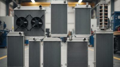
Air-cooled units suit dusty sites when their fins remain accessible for cleaning.
Water-cooled units can perform well where ambient air is hot, but they need careful inspection for leaks and scale.
Fan-driven systems should provide steady airflow across the core, even when the engine runs slowly.
Check inlet temperature, outlet temperature, and reservoir temperature with calibrated sensors. Small differences matter.
Field experience often exposes simple mistakes. I once saw an operator blame weak pump performance when the real problem was a blocked cooler screen.
That assumption was wrong. Clean the core gently, inspect hoses for soft spots, and check oil level before changing major components.
Temperature spikes above 60°C deserve investigation, especially after long loading cycles.
A dirty filter, restricted return line, or failing fan may be responsible.
Do not rely only on the dashboard gauge. It may respond slowly, or read from a cooler part of the circuit. Temperature records from several work shifts provide better evidence for selecting one of the ten most suitable hydraulic cooling systems.
System Selection Criteria: Size Coolers for 25–30% of Hydraulic Input Power
Hydraulic cooling begins with heat-load math, not cooler catalog size. A practical selection rule is to rate the cooler for 25–30% of the hydraulic input power. For a 100 kW power unit, that means rejecting approximately 25–30 kW of heat under demanding conditions. This allowance reflects losses from pumps, valves, cylinders, hose friction, and pressure control. ISO 4413 stresses controlling hydraulic temperature because excessive heat accelerates fluid oxidation, seal wear, and component failure. Field assessments from the U.S. Department of Energy also identify throttling and pressure losses as significant sources of wasted energy.
The calculation still needs adjustment. Measure duty cycle, ambient temperature, oil flow, maximum pressure, and airflow around the machine. A cooler sized only for average load may fail during long digging cycles or summer operation. Check the manufacturer’s heat-rejection curve at the actual oil temperature, not at an optimistic laboratory condition. I have seen systems pass a short test and overheat after several hours. That gap deserves attention.
Tips: Start with 25–30% of input power, then verify the result using measured return-line temperature. Keep the oil below the equipment supplier’s recommended limit, commonly near 80°C for mineral hydraulic fluids. Clean the cooler core regularly. A blocked core can erase much of the expected capacity. Also review fan control, reservoir volume, and installation clearance; cooling performance is a system result, not a single-component promise.
Ten Best Systems: Air-Oil, Water-Oil, Fan-Assisted, and Integrated Designs
Heavy equipment loses hydraulic efficiency quickly when heat stays trapped in the circuit. In field inspections, I have seen oil temperatures rise during slow excavation cycles, even when the machine seemed lightly loaded. Air-oil coolers suit many mobile machines because airflow removes heat through compact finned cores. They are simple to service. However, clogged fins can make a healthy system look defective.
Water-oil coolers transfer heat more consistently in dusty or enclosed areas. They need clean water flow, corrosion control, and careful leak monitoring. A small coolant leak can damage hydraulic oil. Fan-assisted systems improve airflow when natural movement is weak. Variable-speed fans can reduce noise and power loss, but their controls add failure points. Inspect fan blades, guards, wiring, and temperature sensors after severe vibration.
Integrated cooling designs combine the oil cooler, radiator, reservoir, and control hardware in one package. This arrangement saves space and can simplify installation. It may also complicate repairs when one component blocks access to another. My early assumption was that larger cooling capacity always meant better protection. It did not. Oversized components can increase weight, cost, and pressure losses. Selection should follow measured heat load, ambient temperature, duty cycle, oil viscosity, and available airflow. Check the return-line temperature after a full working cycle, not only at idle. That detail often changes the decision.
Heavy-Equipment Comparison: Evaluate Flow, Pressure, Heat Load, and Dust Exposure
When comparing the ten best hydraulic cooling systems for heavy equipment, flow is the practical starting point. A pump may promise high capacity, yet restricted hoses can erase that advantage. Measure flow at operating temperature, not only on a cold test bench. I use a calibrated flow meter and record readings at idle, working speed, and relief pressure. Small differences matter. A loader that loses flow during a long lift feels slow before it shows a fault.
Pressure tells a different story. The cooler must survive the circuit’s maximum working pressure, including short pressure spikes. Compare rated pressure with the machine’s relief-valve setting and hose configuration. Do not treat a higher pressure rating as automatic proof of better cooling. Heat load depends on horsepower converted to heat, ambient temperature, duty cycle, and oil condition. During testing, I check inlet and outlet temperatures after thirty minutes of continuous work. A 12°C drop can look impressive, but it means little without oil flow and starting temperature. That comparison is often missed.
Dust exposure changes the ranking on a real worksite. Fine quarry dust can block fins, while crop debris may form a damp mat. Look for accessible cores, sturdy guards, reversible cleaning options, and clear service space. Measure pressure loss across the cooler as the core becomes dirty. If cleaning requires removing half the assembly, maintenance data will become optimistic. I have made that mistake. A balanced choice may accept slight pressure loss for easier cleaning, but the trade-off needs field records.
10 Best Hydraulic Cooling Systems for Heavy Equipment - Heavy-Equipment Comparison: Evaluate Flow, Pressure, Heat Load, and Dust Exposure
| Rank |
Cooling System Configuration |
Typical Hydraulic Flow
(L/min) |
Continuous Working Pressure
(bar) |
Approx. Heat Rejection
(kW) |
Recommended Ambient
(°C) |
Dust Exposure Suitability |
Fan Control |
Typical Cleaning Interval
(operating hours) |
Best-Fit Heavy Equipment |
| 1 |
Variable-displacement hydraulic oil cooler with thermostatic bypass |
80–220 |
250–350 |
25–55 |
−20 to 45 |
Excellent |
Hydraulic or electronic variable-speed |
50–100 |
Excavators, wheel loaders, forestry machines |
| 2 |
Reversible axial-fan air-oil cooler with protective screen |
60–180 |
210–315 |
18–45 |
−25 to 50 |
Excellent |
Electric or hydraulic variable-speed |
25–75 |
Mining trucks, dozers, aggregate equipment |
| 3 |
Stacked-core hydraulic, charge-air, and engine radiator package |
100–300 |
250–350 |
35–75 |
−20 to 45 |
Good |
Engine-driven or electronically controlled |
25–50 |
Large loaders, articulated haulers, crawler tractors |
| 4 |
Remote-mounted fan cooler with long hydraulic hose installation |
50–160 |
210–315 |
15–40 |
−30 to 50 |
Excellent |
Variable-speed electric |
50–100 |
Compact loaders, underground equipment, demolition machines |
| 5 |
High-capacity parallel-core air-oil cooler |
150–400 |
280–350 |
45–100 |
−15 to 45 |
Good |
Hydraulic variable-speed |
25–50 |
High-flow excavators, drilling rigs, material handlers |
| 6 |
Water-cooled plate heat exchanger with separate cooling circuit |
40–250 |
250–400 |
25–90 |
5 to 40 |
Excellent |
External water-flow control |
250–1,000 |
Marine construction equipment, tunneling machines, fixed power units |
| 7 |
Compact fan-assisted return-line cooler |
25–100 |
160–250 |
8–25 |
−20 to 45 |
Good |
Fixed-speed electric |
50–100 |
Skid steers, backhoe loaders, small excavators |
| 8 |
Heavy-duty fin-and-tube oil cooler with coarse pre-screen |
60–200 |
210–315 |
18–50 |
−25 to 50 |
Good |
Engine-driven fixed-speed |
25–75 |
Agricultural tractors, balers, harvesters, graders |
| 9 |
Fanless hydraulic-to-water heat exchanger for enclosed installations |
30–180 |
250–400 |
15–60 |
5 to 40 |
Excellent |
Water-flow regulated |
250–1,000 |
Underground loaders, indoor cranes, enclosed recycling equipment |
| 10 |
Electrically driven microchannel cooler with automatic reversing airflow |
40–140 |
210–315 |
12–35 |
−30 to 50 |
Good |
Electronically variable-speed |
50–150 |
Electric construction equipment, compact telehandlers, municipal machines |
Data note: Values are representative engineering ranges for heavy-equipment cooling arrangements. Actual performance depends on oil viscosity, cooler core size, airflow, hydraulic efficiency, duty cycle, ambient temperature, installation clearance, and contamination level. Heat-rejection values should be verified through application-specific thermal testing.
Maintenance Standards: Control Fouling, Pressure Drop, Leaks, and 82°C Limits
Heavy equipment cooling systems must control fouling, pressure drop, leaks, and the 82°C operating limit. ISO 4406:2017 classifies hydraulic cleanliness by particle counts at 4, 6, and 14 microns. A rising code signals contamination before valves respond slowly or pumps wear. Inspect return-line filters, cooler passages, and breather elements during scheduled service. Fouling often hides behind acceptable oil color.
Measure pressure across the cooler when the oil is warm. The U.S. Department of Energy’s hydraulic efficiency guidance identifies excessive pressure and leakage as major energy losses. A sudden pressure increase usually indicates blocked fins, restricted passages, or thickened oil. Record inlet and outlet temperatures too. Keep the measured oil temperature below 82°C unless the equipment maker specifies another limit. Hotter oil accelerates oxidation and weakens seals. Small leaks matter.
Use clean sampling bottles and label every sample. ISO 4406 results are useful only when sampling is consistent. That part is often neglected. Check hose crimps, fittings, and cooler joints for wet dust, not just visible drips. A pressure test can expose leaks that appear only under load. Maintenance teams should compare weekly readings, because one perfect inspection cannot prove stable cooling performance. Some assumptions fail in dirty, high-ambient sites. Test again.