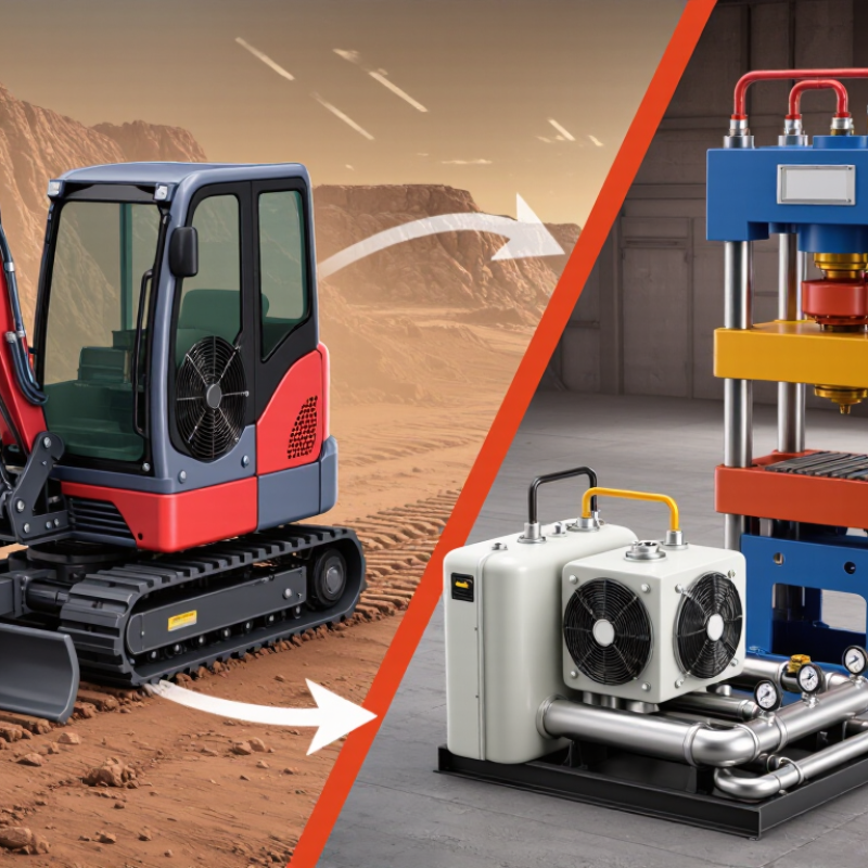
Choosing the right Hydraulic Cooling System is not simply a matter of matching horsepower. It requires a clear view of the machine, operating environment, and heat load. A compact excavator working in a dusty quarry faces different demands than a factory press operating indoors. Oil temperature, ambient heat, airflow, duty cycle, and available installation space all influence the final choice.
Reliable selection begins with measured information. Record the hydraulic fluid temperature during peak operation, not only during a short test. Check the pump flow, system pressure, reservoir size, and expected heat rejection. A cooler that appears adequate on paper may struggle when filters become dirty or airflow becomes restricted. Fan noise, electrical supply, hose routing, and cleaning access also deserve attention. Small details matter.
Experienced engineers usually compare air-cooled and water-cooled designs against manufacturer data and applicable safety standards. They also review material compatibility, corrosion protection, service intervals, and replacement-part availability. These checks support dependable decisions and reduce costly downtime. Still, no selection method is perfect. An impressive calculation can miss seasonal temperature changes. A low purchase price can hide difficult maintenance. The best choice balances thermal performance, reliability, energy use, and long-term service needs. Careful testing remains valuable. A thermometer and pressure gauge may reveal more than a confident assumption. This guide explains the practical factors behind a sound decision, while recognizing that real machines rarely operate under ideal conditions.
How to Choose a Hydraulic Cooling System?
Define Heat Load: Remove 20–30% of Hydraulic Input Power as Heat
Start with heat load, not cooler size. A practical design rule removes 20–30% of hydraulic input power as heat. For a 100 kW power unit, that means approximately 20–30 kW of cooling duty. This estimate suits many continuously loaded systems. It can fail during high-pressure operation, frequent relief-valve cycling, or poor component efficiency. The National Fluid Power Association highlights efficiency losses across pumps, valves, actuators, and pipework. ISO 4413 also emphasizes controlling temperature, pressure, and fluid condition in hydraulic installations.
Measure real conditions when possible. Record inlet and return temperatures, flow rate, pressure, ambient temperature, and operating hours. A thermal camera can reveal hot valve blocks or restricted lines. The U.S. Department of Energy’s Industrial Assessment Centers report that measurement-based assessments often uncover avoidable losses in motor-driven equipment. Do not size the cooler from motor horsepower alone. That shortcut is common, but it is not always reliable.
Tips: Calculate heat using actual duty cycles. Check the worst summer ambient temperature. Keep oil temperature within the fluid manufacturer’s working range. Allow a safety margin, but avoid excessive oversizing. An oversized cooler may reduce temperature too slowly at low flow. Recheck the calculation after commissioning. Field data may disagree with the first estimate. That is normal, and worth investigating.
How to Choose a Hydraulic Cooling System?
Match Oil Temperature: Maintain 30–60°C for Stable Hydraulic Performance
Choosing a hydraulic cooling system starts with oil temperature, not the cooler’s advertised capacity. In field inspections, I measure temperature at the reservoir and return line after reaching a steady load. Keep operating oil between 30°C and 60°C for stable viscosity, sealing, and component response. Below this range, thick oil can slow valves and increase starting pressure. Above 60°C, oxidation and seal wear usually accelerate.
A suitable cooler must remove the machine’s real heat load. Check pump power, duty cycle, ambient temperature, airflow, and reservoir volume before selecting capacity. A temperature-controlled bypass can prevent overcooling during cold starts. It also reduces unnecessary fan operation. The calculation is easy to overlook. Actual conditions often differ from laboratory ratings. Manufacturer viscosity limits and hydraulic calculations should guide the final decision.
Install sensors where they reveal useful information, especially near the return line and reservoir outlet. Record readings during startup, peak load, and shutdown. The control panel may look reassuring. It is not proof. Dust-covered fins, restricted airflow, or low oil levels can push temperatures upward without immediate alarms. I once trusted a single reservoir reading and missed a hotter return line. That mistake changed my inspection routine. Check filters, hoses, fan direction, and cooler cleanliness regularly. Seasonal testing matters too. A system stable at 35°C in winter may approach 60°C during summer production.
| Oil Temperature Condition | Typical Operating Status | Hydraulic Performance Risk | Recommended Cooling Action | Suitable Cooling System Characteristics | Monitoring Priority |
|---|---|---|---|---|---|
| Below 30°C | Oil may be cold during start-up, in low-ambient conditions, or after long periods of shutdown. | Higher viscosity can increase pump inlet resistance, pressure losses, and actuator response time. | Warm the system gradually before demanding full load. | Use a controlled start-up procedure; consider an oil heater where low ambient temperature is expected. | Check viscosity, pump noise, suction conditions, and filter differential pressure. |
| 30–45°C | Generally favorable operating range for many mineral-based hydraulic oils. | Stable viscosity, sealing behavior, lubrication, and component response are more likely when the oil grade is correctly selected. | Maintain this range when practical through normal heat rejection and controlled cooling. | Air-cooled or water-cooled systems can both be suitable, depending on ambient conditions and available utilities. | Verify oil temperature at the reservoir or return line and track trends during peak duty cycles. |
| 45–60°C | Common working range for many industrial hydraulic systems under moderate to heavy load. | Oil aging accelerates as temperature rises; viscosity decreases and leakage may increase. | Use active cooling if the temperature remains near the upper limit or continues to rise. | Size the cooler for the actual heat load, oil flow, ambient temperature, and allowable pressure drop. | Check cooler performance, airflow or water flow, reservoir cleanliness, and return-line temperature. |
| Above 60°C | Temperature is higher than the preferred stable operating band stated for this selection guide. | Accelerated oil oxidation, reduced viscosity, seal damage, leakage, and shortened component life may occur. | Reduce heat generation and restore temperature before continuous operation. | Use a larger or more effective cooler, improve ventilation, or review pump efficiency, relief-valve settings, and internal leakage. | Inspect immediately for blocked cooler surfaces, insufficient airflow or water flow, overloaded equipment, and incorrect oil level. |
| Above 80°C | Severe overheating or abnormal operating condition. | Rapid oil degradation and possible damage to seals, pumps, valves, hoses, and other hydraulic components. | Stop or unload the equipment safely and identify the root cause before restarting. | Do not rely only on a larger cooler; investigate excessive pressure losses, relief-valve flow, mechanical inefficiency, and contamination. | Use an alarm or shutdown sensor and perform a complete system inspection. |
| Selection note: Choose the cooler from the measured heat load rather than oil temperature alone. Confirm the hydraulic flow rate, maximum system pressure, oil type and viscosity, inlet oil temperature, ambient temperature, allowable pressure drop, available space, and required heat-rejection capacity. The 30–60°C range is a practical selection guide; always follow the hydraulic equipment and fluid manufacturer’s specified operating limits. | |||||
How to Choose a Hydraulic Cooling System?
Choosing a hydraulic cooling system starts with the hottest operating condition, not the average workshop temperature. Above 40°C, an air cooler may lose performance because the air-to-oil temperature difference becomes smaller. Dusty fins and slow fans make this problem worse. Air cooling is simple, leak-resistant, and practical where clean airflow is available. It also needs enough space around the cooler.
Water cooling usually removes heat more efficiently in hot environments. A steady water supply can maintain a lower oil temperature, even when ambient air reaches 45°C. However, water quality matters. Scale, corrosion, blocked passages, and unstable water pressure can reduce performance. A strainer, flow monitor, and regular inspection are sensible safeguards.
Check the cooler’s rated ambient limit carefully. Do not select a unit using normal daytime temperatures alone. Measure the enclosure temperature near the hydraulic tank, where heat often collects. I have seen systems pass factory testing but run too hot during summer production. The original estimate was optimistic. Oil temperature, flow rate, duty cycle, and allowable pressure drop must be checked together. A larger cooler may help, but excessive cooling can increase oil viscosity during startup. When air temperature stays above 40°C, water cooling often offers more stable control, while air cooling may still work with forced ventilation and generous capacity. Conditions change. Recheck them.
Compare air, water, and ambient cooling options by typical heat-transfer capability and suitability when ambient temperature rises above 40°C.
Guidance: Air cooling is simple and reliable but becomes less effective as ambient temperature increases. Water cooling provides substantially higher heat-transfer capability and is often preferred for high heat loads or hot environments. Ambient or passive cooling has the lowest capacity and is suitable only when heat generation is limited and the surrounding air remains relatively cool.
Choosing a hydraulic cooling system starts with the machine’s real operating data, not a catalog estimate. Record the rated flow, working pressure, fluid temperature, and ambient temperature during the hardest duty cycle. A cooler rated for 60 L/min may perform poorly if the system regularly reaches 75 L/min. Excess flow can increase pressure drop and reduce available actuator force.
Check pressure drop across the cooler, hoses, valves, and filters. Measure pressure before and after the cooler with calibrated gauges. The difference should remain within the pump and circuit limits at maximum flow. A small pressure drop is valuable. It reduces wasted energy and unwanted heat. Also verify the cooler’s heat rejection at the actual oil temperature, airflow, and ambient conditions. A published capacity at ideal laboratory conditions may not match a dusty enclosure.
Heat rejection should exceed the calculated heat load, usually with a practical margin of about 10 to 20 percent. Calculate heat from measured input power, operating time, and temperature rise when possible. Do not rely only on reservoir size. Larger tanks delay overheating but do not remove heat. They can hide an undersized cooler.
Field conditions matter. Clean airflow paths regularly. Inspect fan performance and fin blockage. A neat spreadsheet can still mislead. I have seen systems pass a paper check but overheat during slow, high-pressure work. Recheck the selection after installation, because actual flow and pressure drop often differ from the design assumptions.
A cooling system can perform poorly when its oil is unsuitable. Begin by checking the required viscosity range. ISO VG 32–68 oil is commonly specified for hydraulic applications, but the correct grade depends on operating temperature and pump design. ISO VG refers to viscosity measured at 40°C, not every working condition. A fluid that seems suitable at room temperature may become too thick during startup or too thin near a hot reservoir. Measure actual temperatures.
Do not inspect the oil alone. Compare its additives with every wetted material, including seals, hoses, gaskets, coatings, fittings, and the heat exchanger core. Nitrile, fluorocarbon, polyurethane, and EPDM compounds can react differently to mineral-based fluids and additive packages. Check technical data sheets and written compatibility charts before filling the circuit.
Small incompatibilities may appear as swollen seals, softened hoses, leaks, or dark residue around joints. Early signs matter.
Field checks should include a clean sample, fluid identification, and a review of the machine’s service records. Flush unknown oil before mixing it with a new formulation. Mixing can change viscosity and reduce additive performance. It is tempting to rely on a familiar ISO grade, yet that shortcut can cause trouble. I have seen systems run quietly while a seal slowly expanded inside a valve block. The cooling capacity looked acceptable, but the material choice was wrong. Recheck compatibility after temperature changes, maintenance, or a fluid conversion.